STATUS: Done! (Nov 14, 2015).
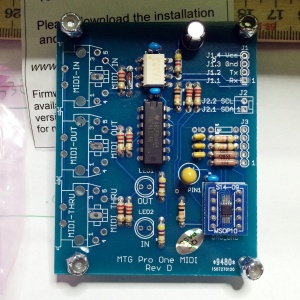
I bought the MTG Turbo CPU replacement, the extra MIDI board, and the CV option (to control filter and stuff via midi).
Check out Music Technologies Group Turbo CPU here!
 The Turbo CPU board replaces the original Pro-One CPU and fits right in the old CPU socket. The main reason for me to get it was that there was a MIDI option for it as well. There are other benefits such as faster performance (although this may border on unnoticable) and also completely new features such as an extra LFO (which I probably won’t use).
The new CPU board
The Turbo CPU attaches to the separate MIDI board with 6 wires. 4 for MIDI, 2 for the extra CV stuff that will control pitch bend, cutoff etc over MIDI.
Step 1 – soldering the 6 wires to the CPU board

Step 3 – drilling holes in PCB for cable ties

Step 4 – mounting new CPU board and cable ties

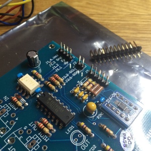
I added molex connectors to the board and the 6 wires so that the Pro-One lid (which has the PCB with the CPU) can be detached from the bottom (which has the MIDI board and connectors)
Step 1 – Molex Connectors on MIDI board
Step 2 – Molex connectors on wires from main PCB

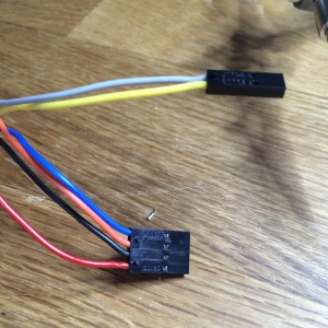
Step 3 – MIDI board wiring (MIDI connectors and LEDs)

Step 4 – Mounting MIDI connectors
Step 5 – Mounting MIDI board and connecting it all
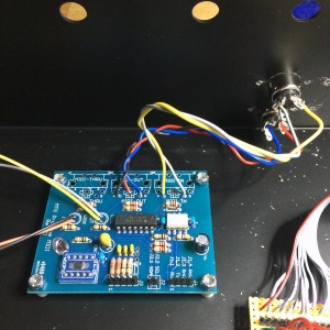
Now I did a quick test of both MIDI In and Out – all working!
The CV connections
The remaining 5 pin connector is for the wires with CV signals going from the MIDI board and back to the main PCB (for pitch bend, filter control etc over MIDI).
Step 1 – soldering 2 wires to control Filter Cutoff and Resonance

Step 2 – soldering 2 wires to control Osc 1&2

Step 3 – soldering molex connector in the other end

Another test. Now I could control pitch bend over MIDI! The range defaults to 2 semitones, nicer than the Pro-One’s “about a fifth” and much more playable (Looking at you, non-spring loaded pitch bend wheel). I also had control over filter resonance and cutoff (connected to mod wheel and using the extra LFO of the new CPU.. not sure how I like this, but it’s all configurable).
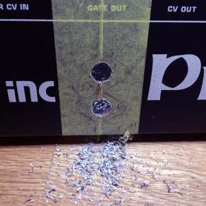
Finally I pushed the MIDI LEDs into the holes drilled in the chassis.
They are ‘modern’ bright blue LEDs – not a big fan.. Maybe I’ll replace them with something more retro like green or red in the future.
Here is an overview pic of the internals (the bigger brownish board is from my keybed replacement mod):
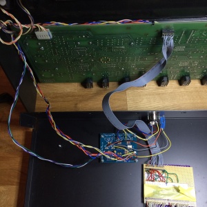
There – all done!


